V9D Robot
Indoor 360° Virtual Tour Assistant
V9D Robot is a team project designed to reduce the manual work involved in creating indoor virtual tours. It combines a mobile platform and height-adjustable 360° camera with a ROS 2 navigation stack. The software connects Cartographer mapping, AMCL localization, Nav2 obstacle avoidance, and map-based capture-waypoint generation, supported by a robot model and indoor environment in Gazebo.
Demonstration
Hardware Design
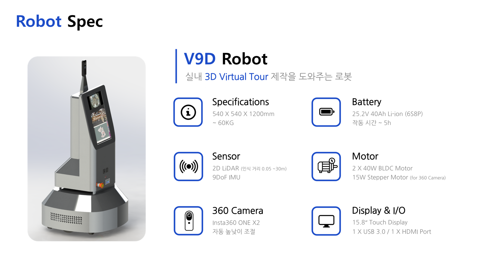
The final design combines a two-motor mobile base, LiDAR and IMU sensing, an Intel NUC computer, and an Insta360 ONE X2 camera on a powered height-adjustment mechanism. A front-mounted touch display provides access to the tour-creation workflow.
- Dimensions
- 540 × 540 × 1200 mm
- Design weight
- Approximately 60 kg
- Drive system
- Two 40 W BLDC motors
- Camera lift
- 15 W stepper motor and linear stage
- Sensors
- RPLiDAR S2, with a 0.05–30 m sensing range, and a 9DoF IMU
- Camera
- Insta360 ONE X2 with automatic height adjustment
- Compute and interface
- Intel NUC, 15.8-inch touch display, USB 3.0, and HDMI
- Power
- 25.2 V, 40 Ah Li-ion battery (6S8P); estimated operating time of about 5 hours
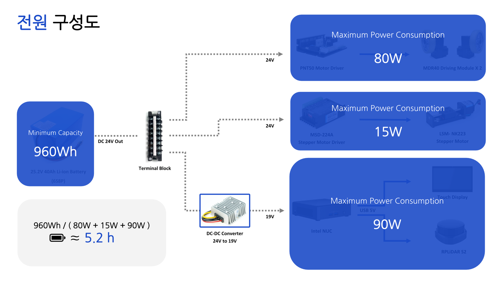
The power-distribution design supplies the drive motors and camera lift from the main battery and uses a DC–DC converter for the computer and peripherals. Operating-time figures are design estimates.
Robot Model and Simulation
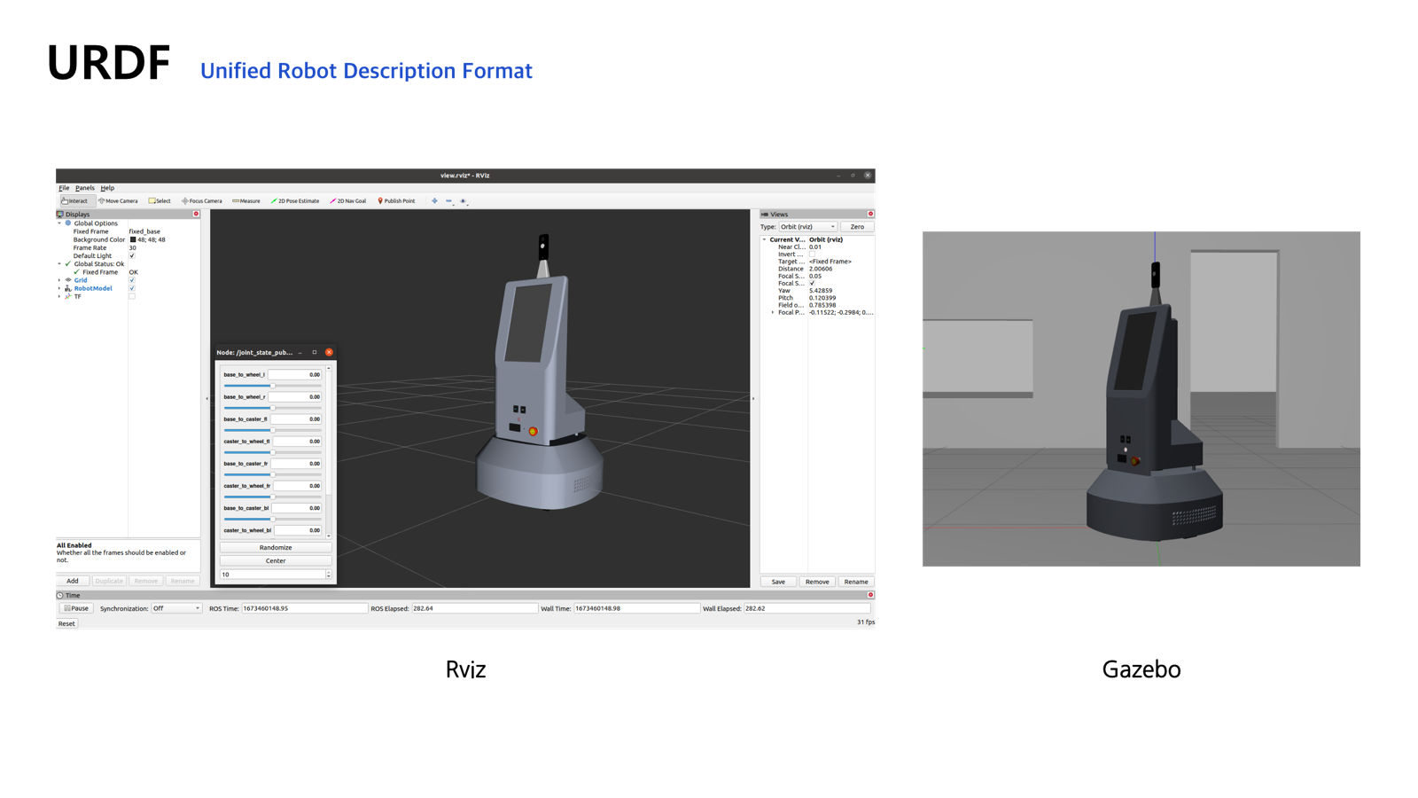
The robot is represented in URDF with links and joints for the chassis, driven wheels, caster assemblies, LiDAR, and camera. Visual meshes, collision geometry, and inertial properties support displaying the model in RViz and running it in Gazebo.
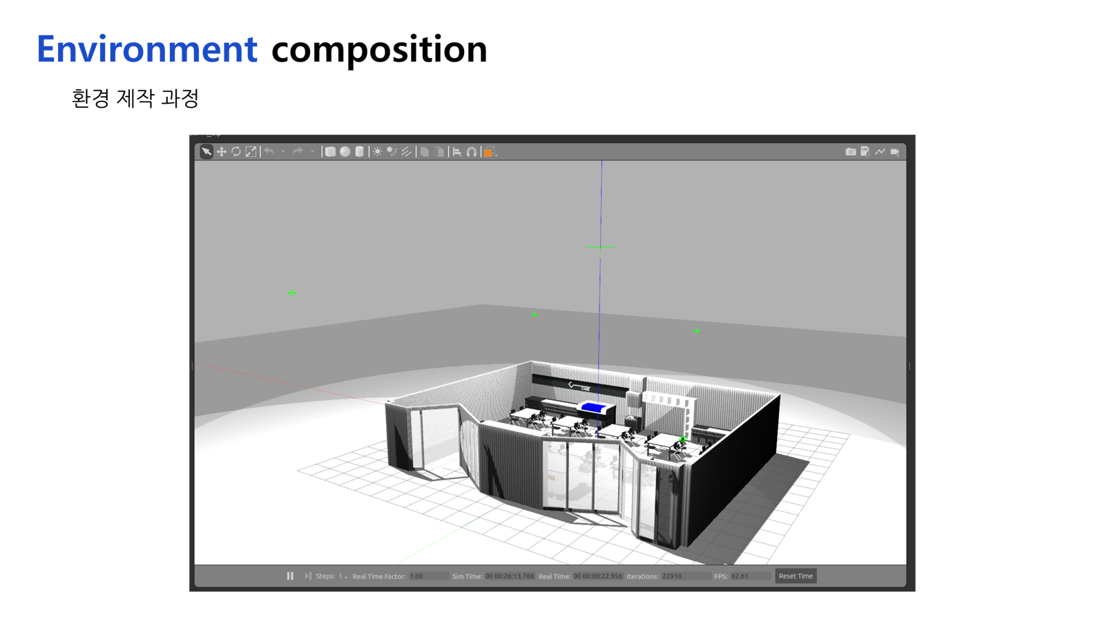
The camera housing is modeled as visual and collision geometry, while separate front and rear camera plugins generate wide-angle simulation images. A simulated LiDAR supplies range observations. The indoor test world includes walls, doors, desks, and chairs to represent the geometry the robot must navigate.
ROS 2 SLAM and Obstacle-Avoidance Navigation
The software framework uses ROS 2 Foxy and Nav2, separating map creation, localization, and local motion control.
Mapping with Cartographer
Cartographer processes LiDAR observations to construct an indoor occupancy map. Scan matching aligns observations as the robot moves, providing the map used by subsequent localization and navigation tasks.
Localization with AMCL
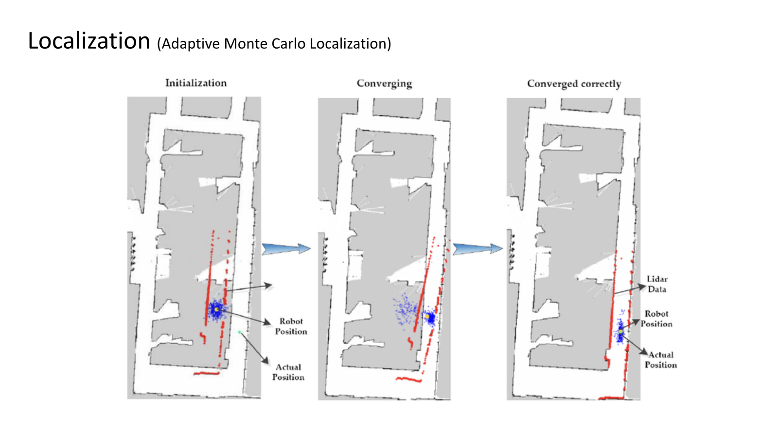
Adaptive Monte Carlo Localization (AMCL) estimates the robot’s pose on the saved map using a particle-based representation of position uncertainty. Aligning incoming LiDAR observations with the map allows the pose estimate to converge and supports navigation between capture locations.
Local Control with DWB
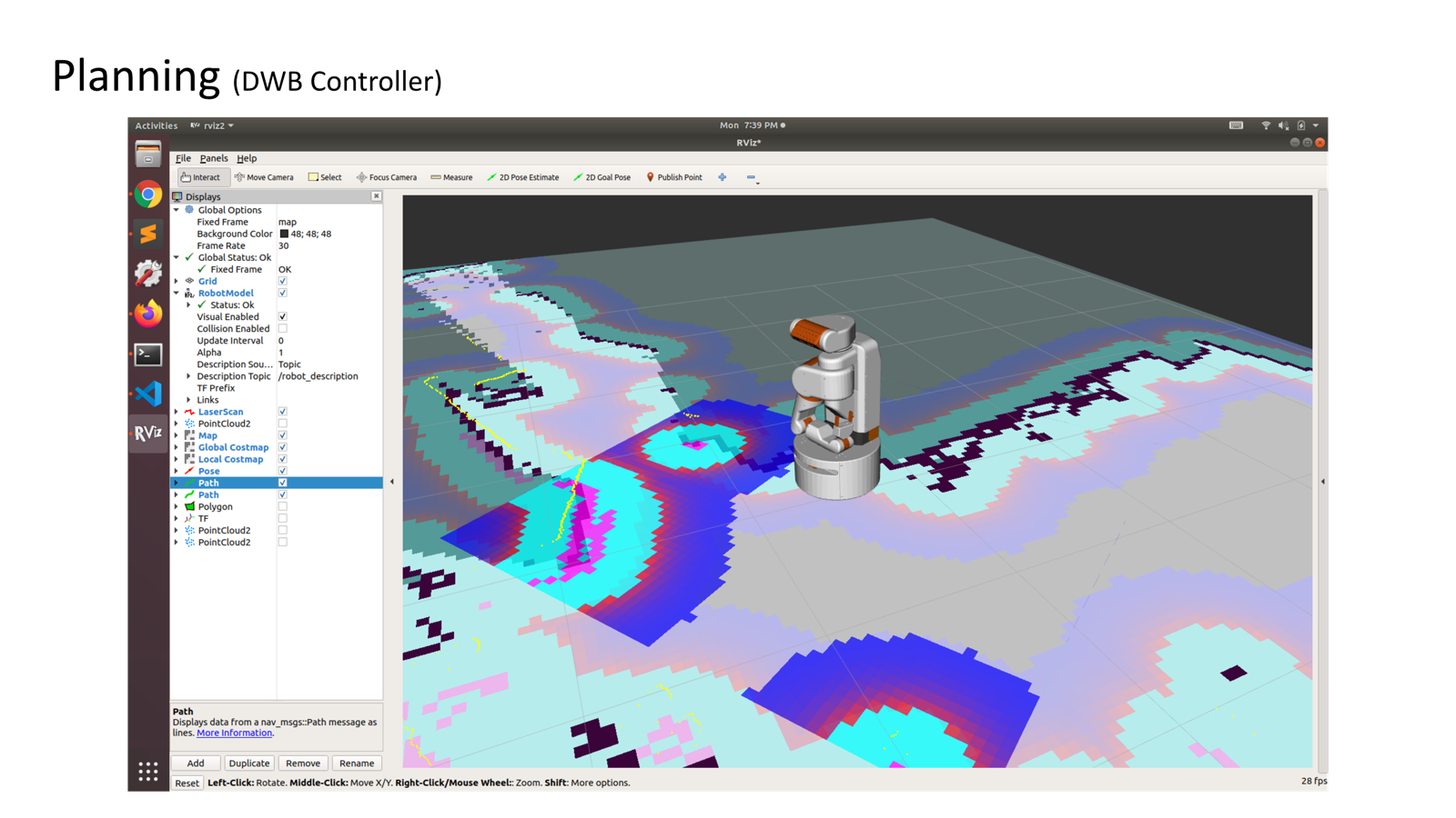
Nav2’s DWB controller handles local motion for path following and obstacle avoidance. It evaluates candidate motions against the path and costmap to select velocity commands for the robot. This local control connects the navigation goals to obstacle-aware movement through the indoor environment.
Capture Waypoint Generation
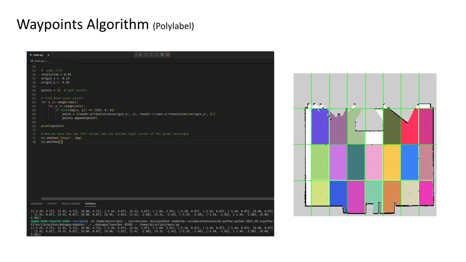
Capture locations are generated from the occupancy-map image using Polylabel. The approach selects points inside free-space contours, favoring interior clearance even when a region is concave and its geometric centroid may lie outside the usable space.
- Divide the map image into an N × M grid of regions of interest.
- Extract free space by thresholding the white regions and finding their contours.
- Filter small regions using the contour-area threshold.
- Apply Polylabel to select an interior capture point for each retained contour.
- Convert pixels to map coordinates using the resolution and origin from
map.yaml, accounting for the image’s vertical-axis direction.
The generated map-frame points become candidate navigation goals. The implementation also references Nav2 Simple Commander for sequencing navigation tasks.
360° Capture and Tour Visualization
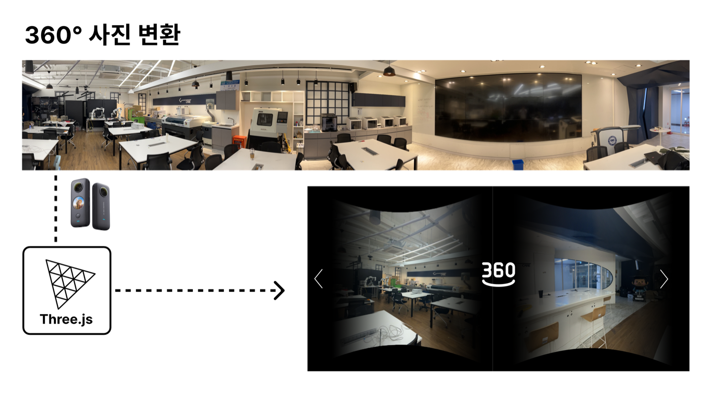
The camera captures panoramic views at selected locations, with its height adjusted by the lift mechanism. The visualization design uses Three.js to display panoramic imagery on a spherical mesh, allowing the viewer to look around each captured scene.
Connecting these views and adding location markers forms the intended virtual-tour workflow. Indoor maps support robot navigation, while the panoramic images provide the visual experience of the tour.
User Workflow
The intended interaction starts from the robot’s touch display and connects the navigation stack to tour creation:
- Create or load an indoor map and initialize the robot’s pose.
- Generate capture waypoints from free-space regions in the occupancy map using Polylabel.
- Navigate between capture points with AMCL localization and Nav2’s DWB controller for local obstacle avoidance.
- Capture and save panoramic views at the selected locations as the navigation sequence progresses.
- Connect the views and add location markers to prepare the virtual tour for exploration.
Contribution
I worked on SLAM and obstacle-avoidance navigation within the ROS 2 system. My contribution focused on integrating indoor mapping, robot localization, and Nav2-based navigation so the robot could move between capture waypoints while accounting for obstacles in its surroundings.