Robot Vision System
Vision-Based Autonomous Driving on the ERICA Campus
This vision-system design project developed a camera-based autonomous driving system for a Unity model of the Hanyang University ERICA campus. The simulated vehicle used its front camera to follow lane markings, read traffic lights, and detect stop lines. A ROS 2 controller combined those observations with the vehicle’s simulated position to decide when to steer, slow down, or brake.
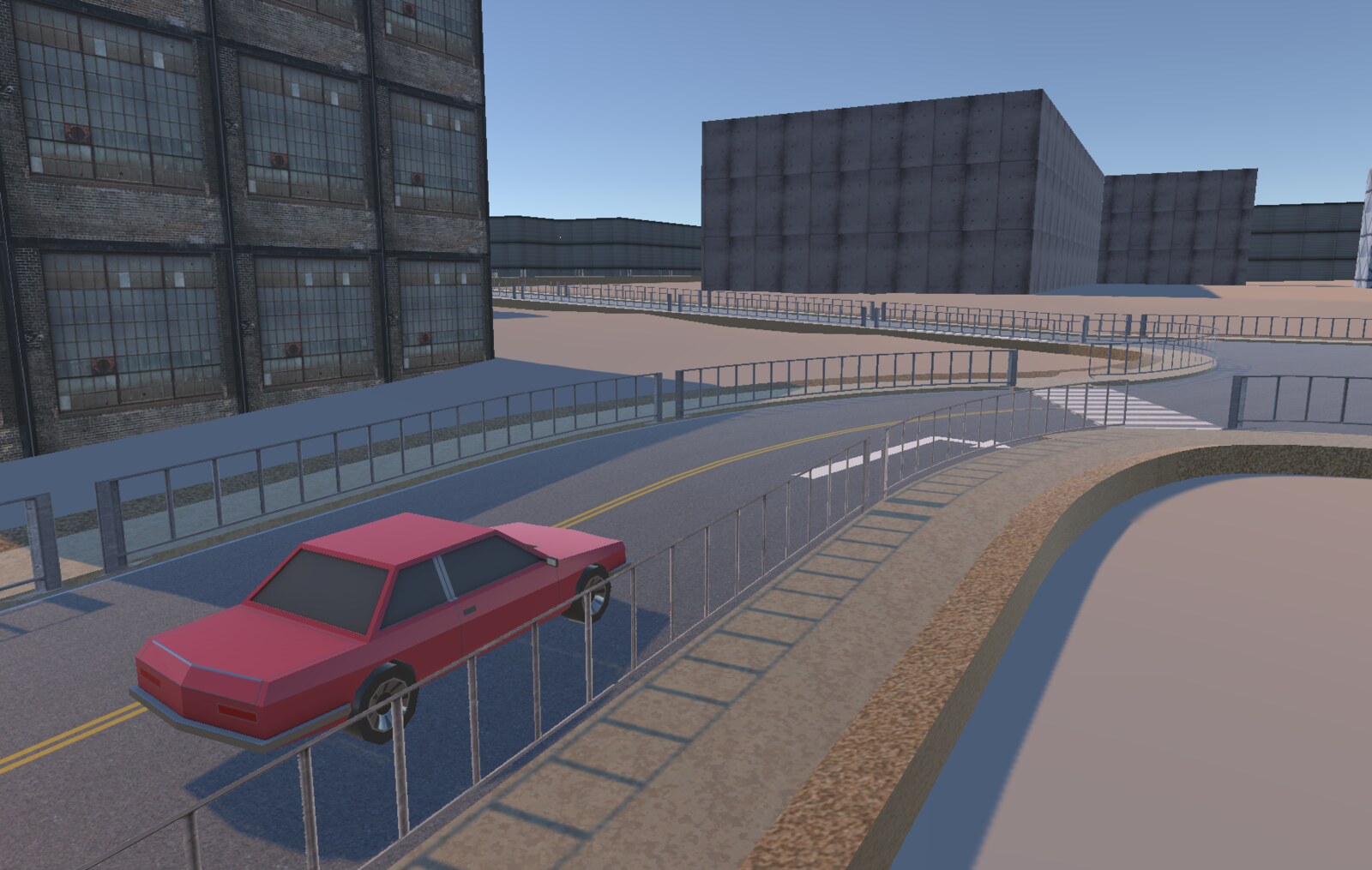
Driving Demonstration
Campus Route and Simulation
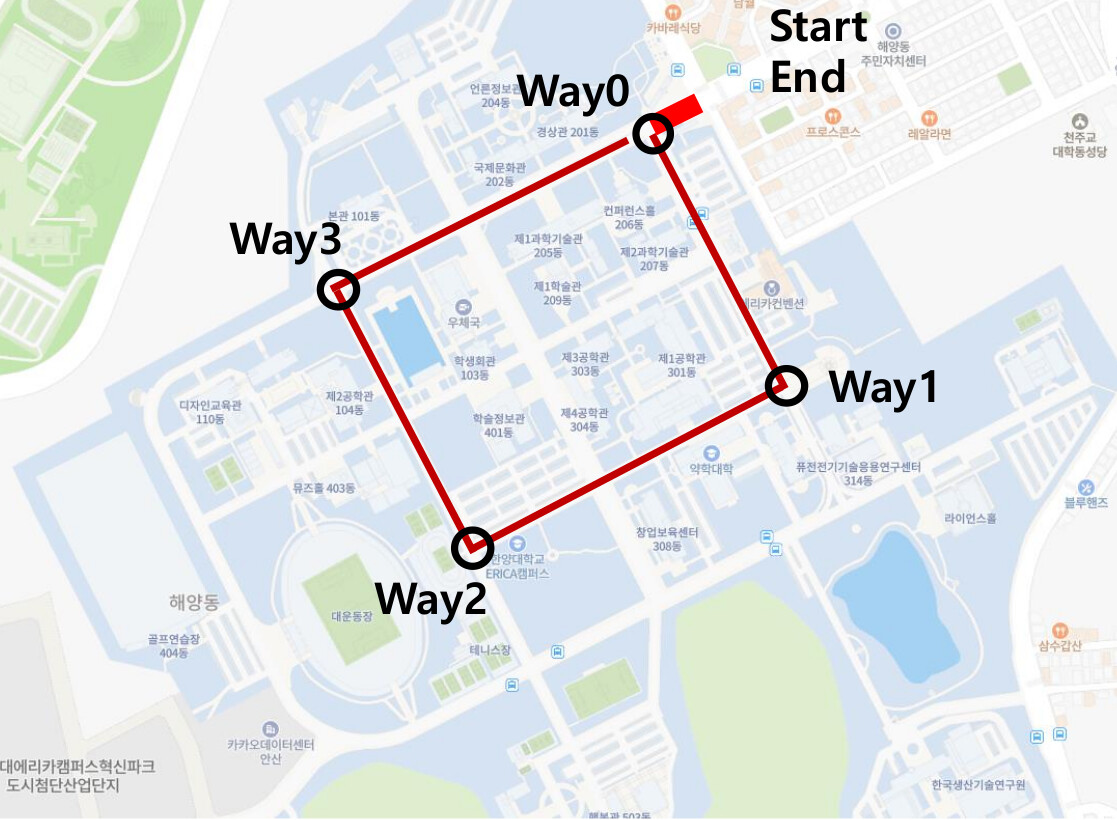
The assignment defined a four-waypoint loop through the campus, with a shared start and finish near Way 0. The Unity road network reproduced the campus setting with curves, lane markings, and intersections. Between intersections, the vehicle followed the visible lane boundaries. At selected junctions, position ranges identified where the controller should apply the route-specific rules.
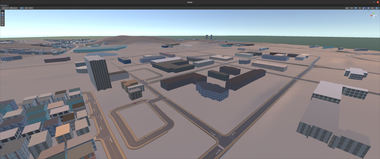
Unity and ROS 2 Integration
The ROS TCP Endpoint connected Unity to the Python ROS 2 nodes. Unity supplied front-camera frames and vehicle state. The lane, traffic-light, and stop-line detectors ran as separate nodes and published their results to the driving node, which returned steering, motor-speed, and brake commands to the simulator.
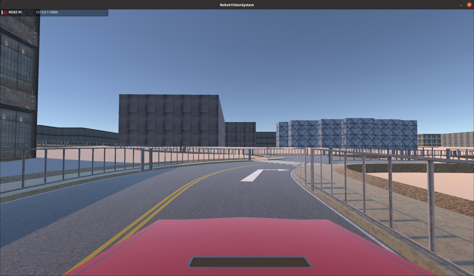
Lane Detection and Steering
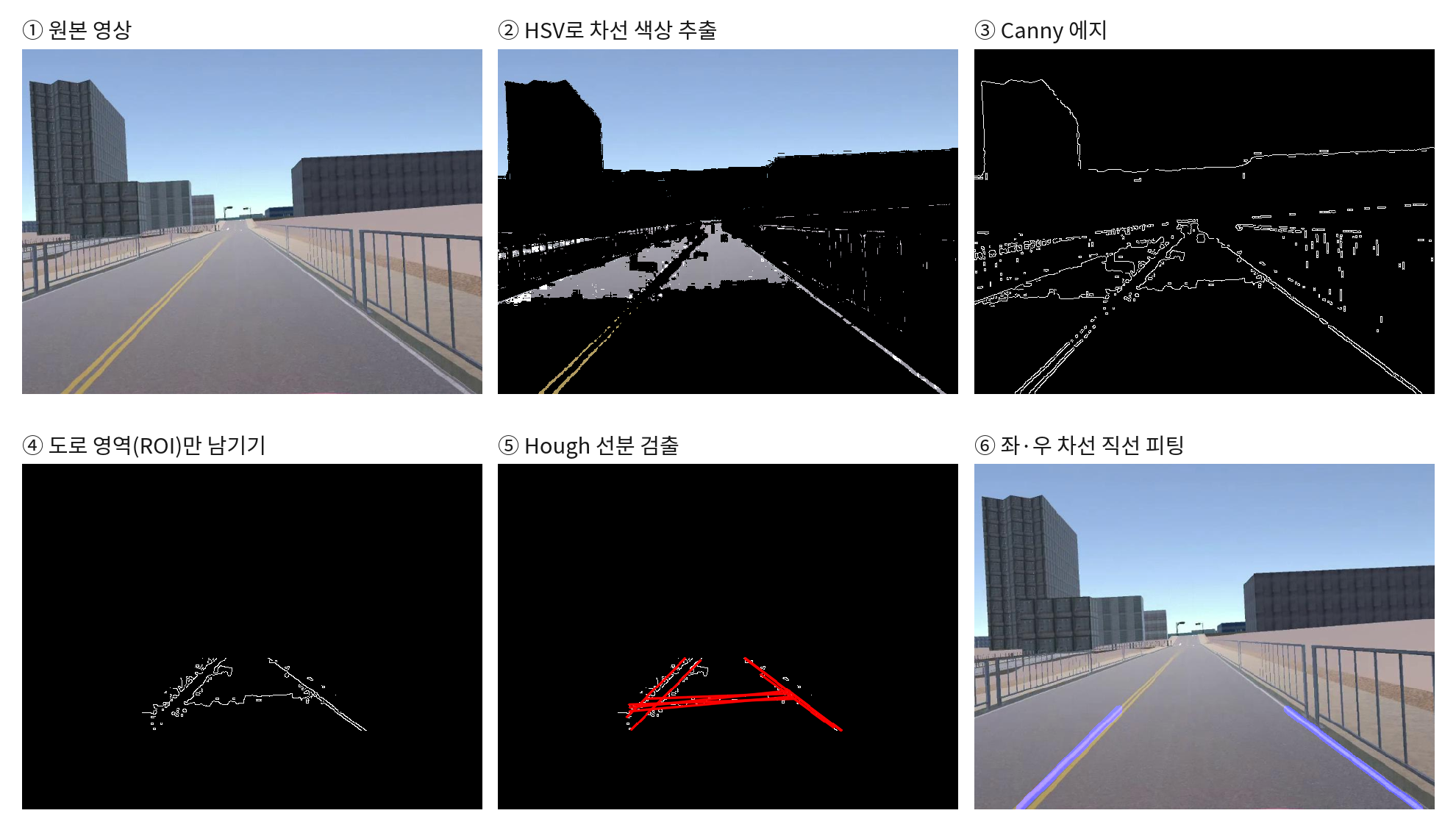
The OpenCV lane detector converted each front-camera frame into a steering reference.
- Isolate lane markings. Use HSV color filtering to retain yellow and white road markings.
- Extract edges. Apply Gaussian smoothing and Canny edge detection, then keep the road region of interest.
- Detect line segments. Use the probabilistic Hough transform and group candidate segments by slope.
- Fit the lane boundaries. Fit a line to each group to estimate the left and right boundary angles.
- Publish a steering reference. Average and scale the fitted angles and send the result to the driving node.
Traffic Lights and Stop Lines
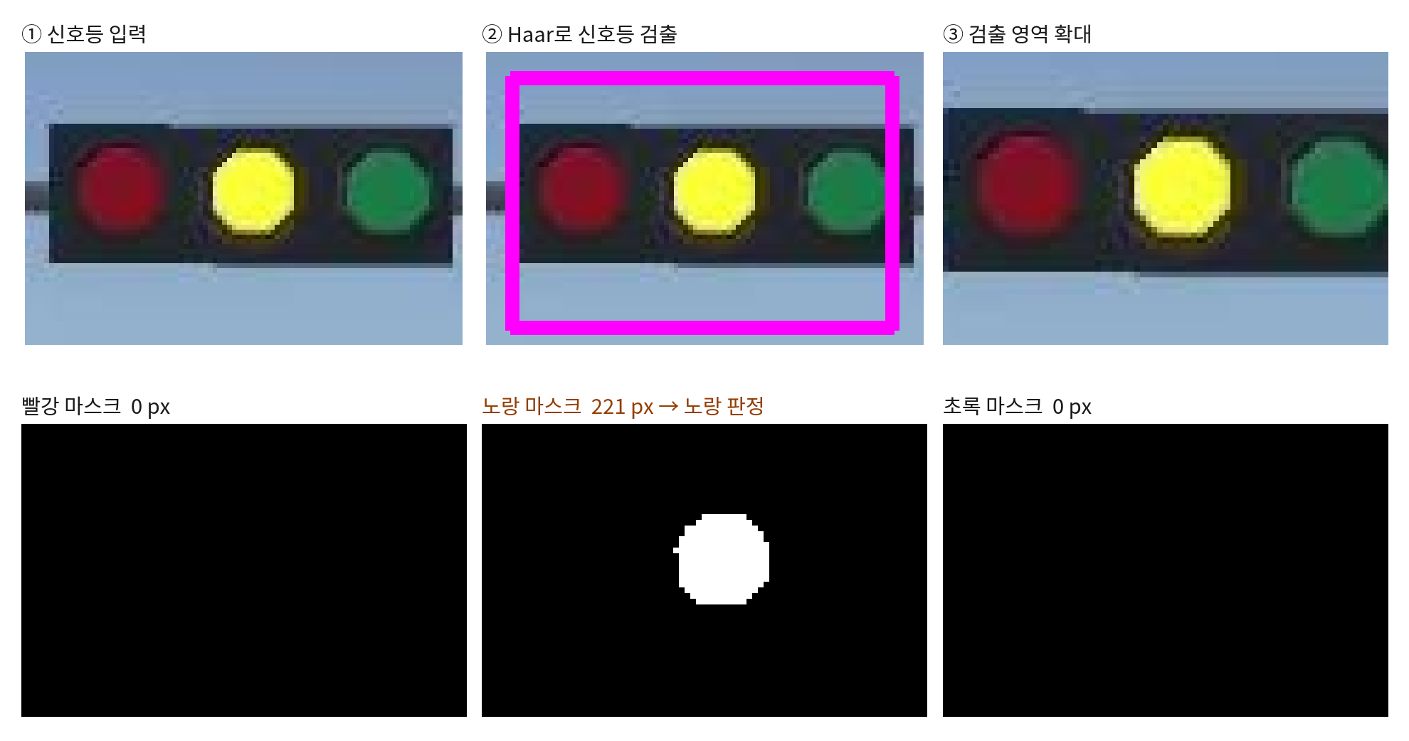
The traffic-light detector estimated the active signal color.
- Select the search region. Keep the upper portion of the frame where traffic lights are expected.
- Locate the signal. Apply a Haar cascade and extract the detected region.
- Classify the color. Compare pixel counts in red, yellow, and green HSV masks and publish the dominant signal color.
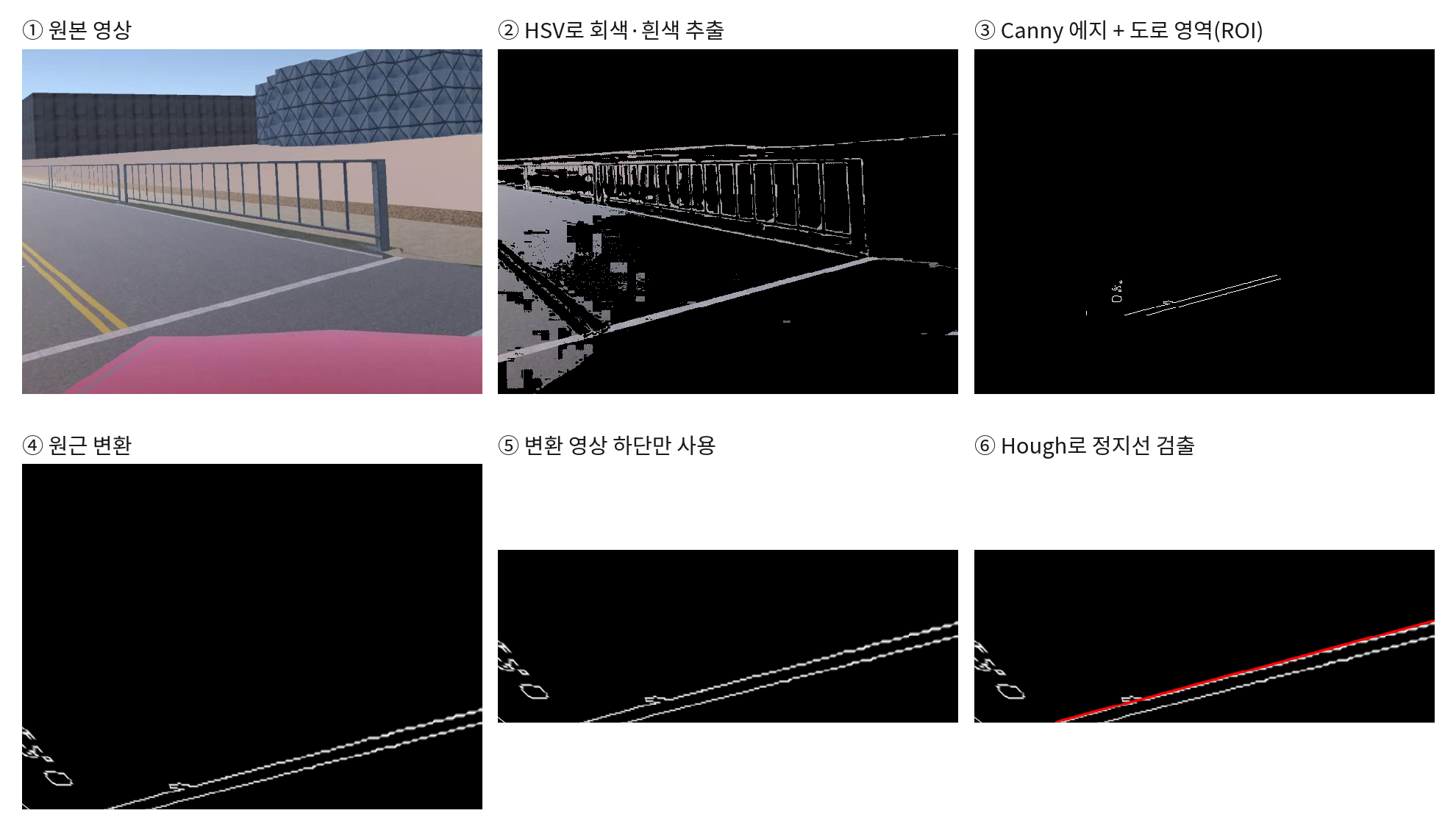
The stop-line detector checked for a road marking directly ahead of the vehicle.
- Filter road markings. Use HSV masks for gray and white pixels, then apply Canny edge detection.
- Isolate the road. Limit processing to the road region of interest and apply a perspective transform to produce a bird’s-eye view.
- Detect a nearby stop line. Search the lower half of the transformed image with the Hough transform and publish a detection when a candidate line is found.
PID Steering and Intersection Control
The driving node used a PID controller for lane following and applied intersection rules based on the detected signal, stop line, and vehicle position.
- Compute the steering error. Compare the lane-derived steering reference with a target of zero.
- Calculate the steering command. Apply the PID controller to the error. The integral gain was set to zero, so the implementation used the proportional and derivative terms.
- Apply the intersection rules. Brake when a red light and a stop line are detected in a configured intersection zone. At selected junctions, a yellow light reduces speed and a green light triggers the configured straight or turning maneuver.
- Send the vehicle commands. Publish steering, motor speed, and brake state back to Unity through ROS 2.
Contribution
I implemented the lane, traffic-light, and stop-line perception nodes and integrated them with the ROS 2 driving controller. I connected the simulator’s camera and state inputs to steering, speed, and brake outputs, so the same system handled lane following and intersection decisions on the planned campus route.