Holo Bot
Shared Scooter Recovery Robot
Holo Bot is a team robotics project for locating fallen or improperly parked shared scooters and assisting their return to a designated personal-mobility parking zone. The work progressed from a mobile-manipulation simulation to a capstone prototype combining outdoor navigation, visual perception, marker-based docking, and a custom lift mechanism.
The system connects a WeGo ST-MINI mobile platform with GNSS, IMU, wheel odometry, LiDAR, and cameras. ROS 2 coordinates the navigation, detection, docking, and lift-control components.
Demonstration
Mission Workflow
The mission logic connects patrol navigation to scooter recovery:
- Patrol the parking area through designated outdoor waypoints and check for scooters outside the parking zone.
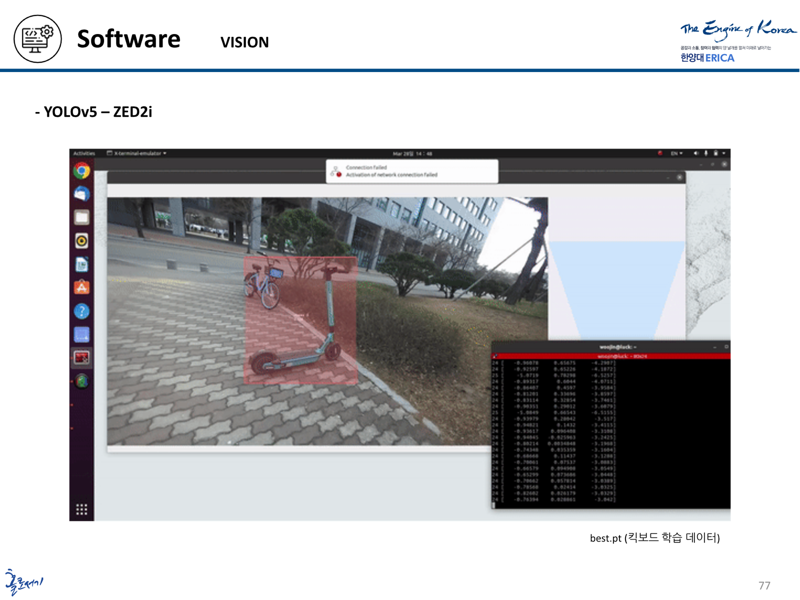
- Detect a scooter with YOLOv5 and use depth information to estimate its position.
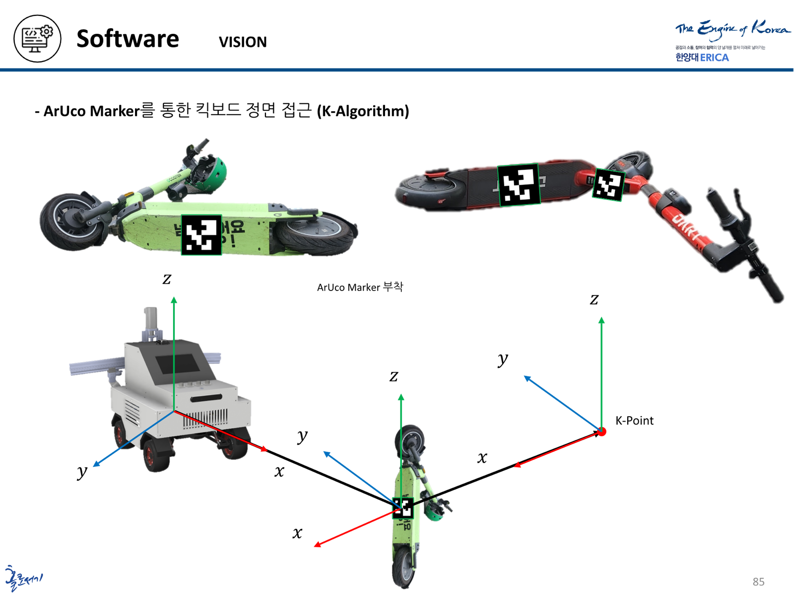
- Establish an approach pose using ArUco-marker observations and the scooter’s coordinate frame.
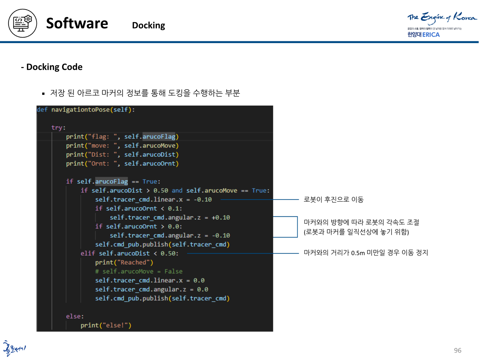
- Turn and dock in reverse, adjusting the robot’s alignment relative to the marker.
- Operate the lift and gripper, then hand control back to navigation for the intended return to the parking zone.
From Simulation to Prototype
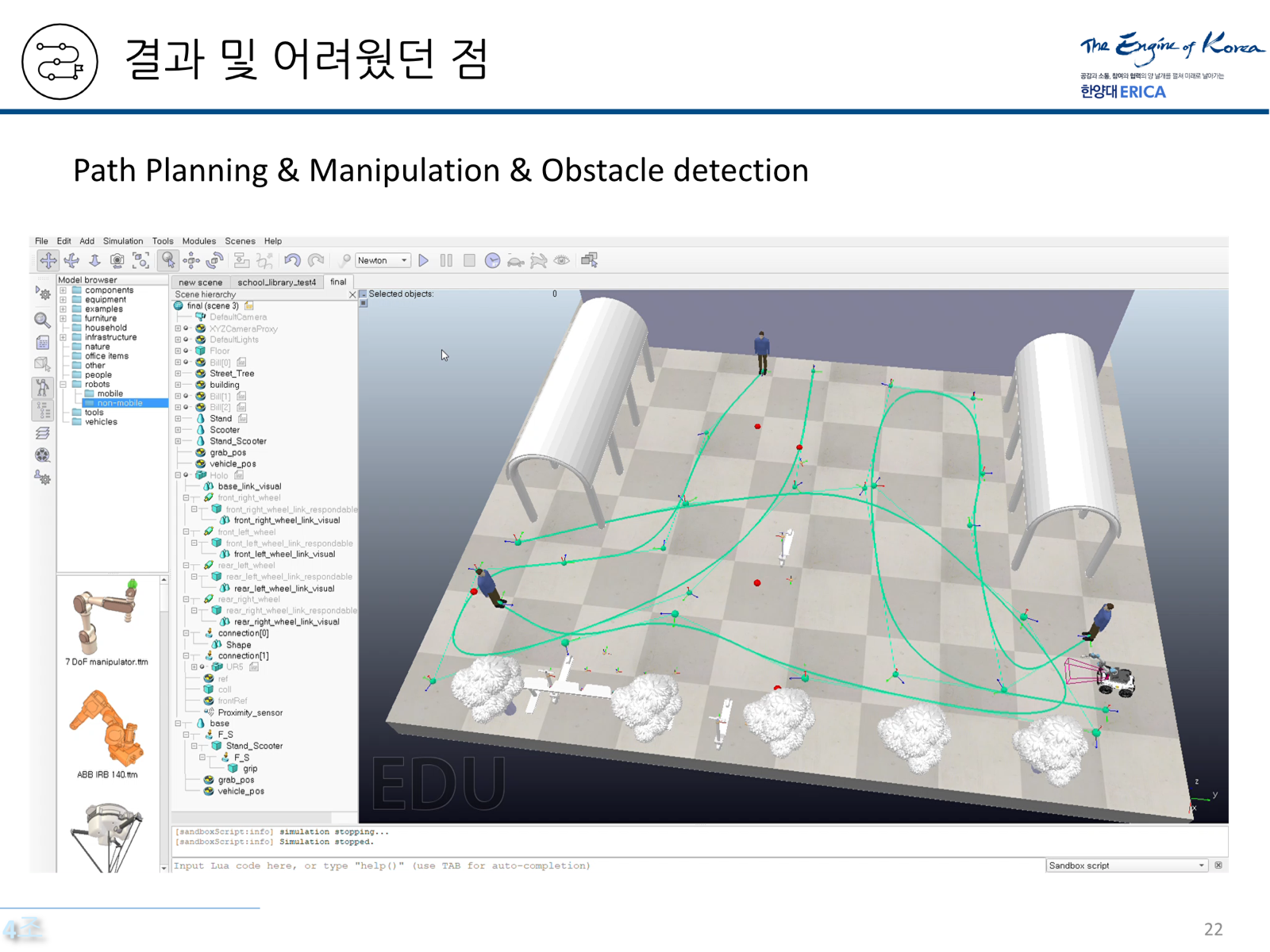
The initial study used V-REP to explore mobile manipulation. A mobile base and UR5 arm approached and grasped a scooter model, with BiTRRT-based motion planning and proximity sensing supporting the simulated scenario.
That stage used simulator-provided position information and proximity sensors as substitutes for parts of the intended sensing system. The capstone then developed a physical mobile platform and a dedicated lift mechanism, alongside tests of navigation, perception, docking, and actuator control.
Hardware and Sensors
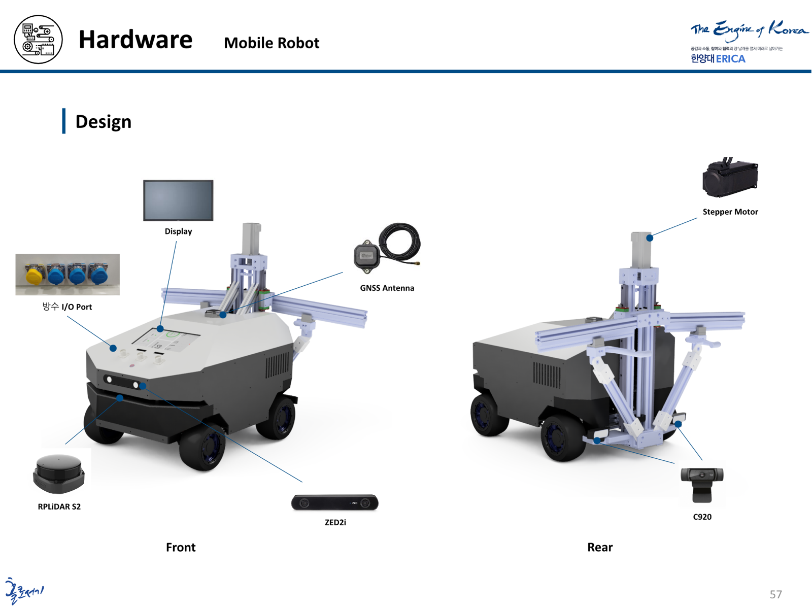
The capstone platform pairs the WeGo ST-MINI base with an upper structure built using profiles, acrylic panels, and printed components. A laptop motherboard provides the main computing platform, while a Raspberry Pi 4B handles the lift-control interface.
- Mobile platform
- WeGo ST-MINI; base dimensions of 612 × 580 × 245 mm
- Depth camera
- STEREOLABS ZED2i for scooter detection and distance estimation
- Docking camera
- Logitech C920 for rear-facing ArUco-marker observations
- Outdoor positioning
- U-blox C099-F9P GNSS receiver, UM7-LT IMU, and wheel odometry
- Obstacle sensing
- RPLiDAR S2 for range observations and navigation
- Controllers
- Intel i7-8750H and GTX 1060 6 GB main computer; Raspberry Pi 4B subcontroller
Outdoor Navigation and Sensor Fusion
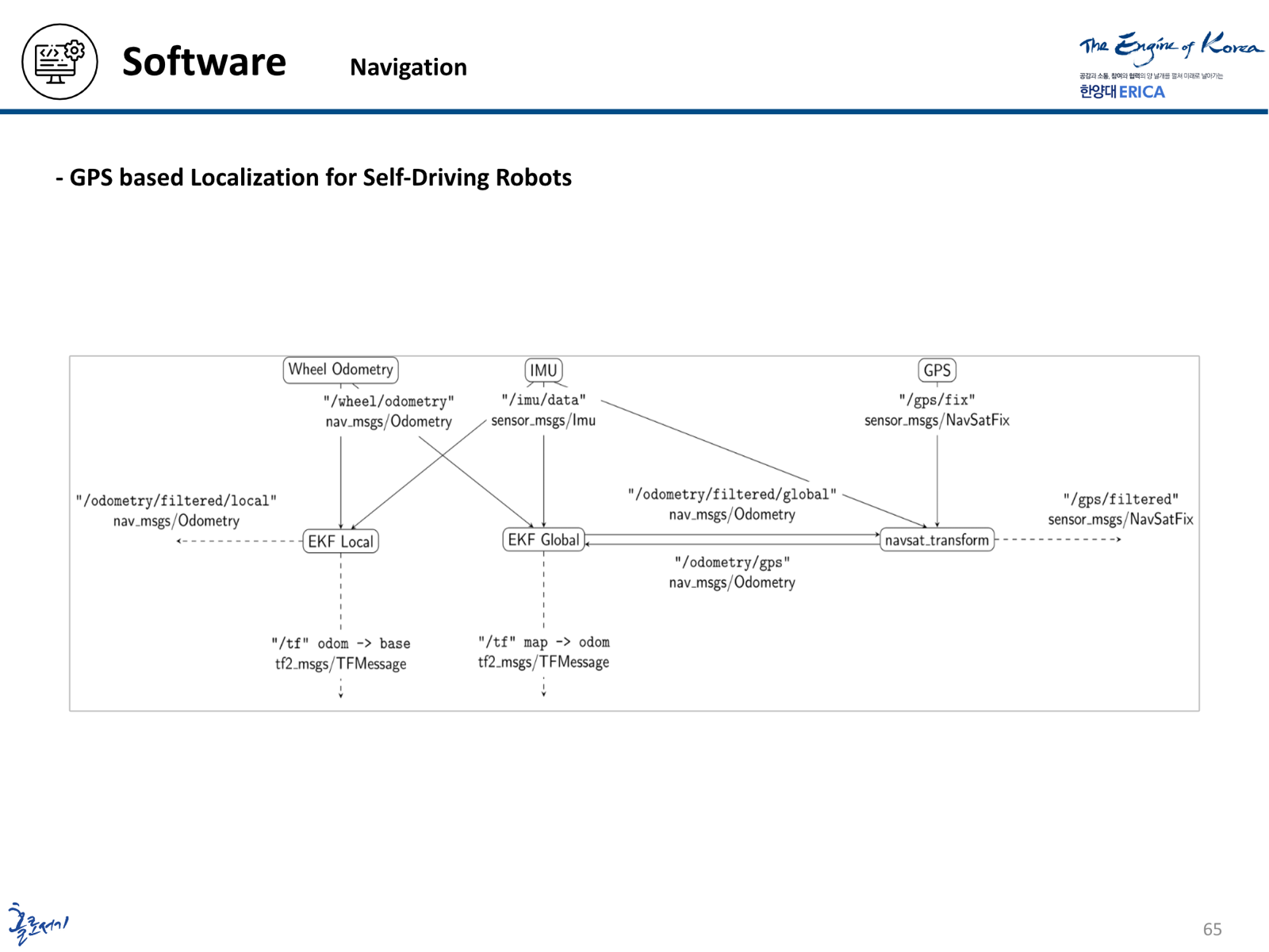
The navigation system uses ROS 2 Nav2 with GPS-coordinate waypoints. The robot_localization package fuses GPS, IMU, and wheel-odometry observations through extended Kalman filters.
The localization architecture separates local and global estimation. Wheel odometry and IMU data feed the local filter, while navsat_transform connects GNSS observations to the map-referenced global estimate. This provides the positioning framework for outdoor waypoint navigation.
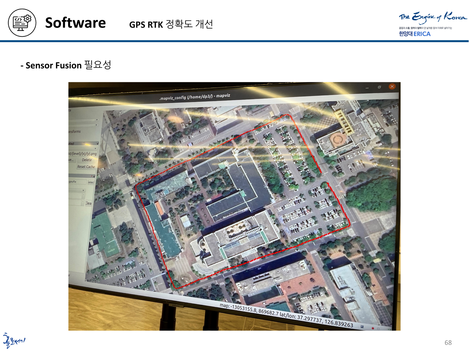
Cartographer mapping tests were also conducted at the campus test field and an indoor engineering-building corridor. The project materials document positioning traces, sensor-fusion observations, and a waypoint-navigation test near the library.
Scooter Perception and Approach
The perception pipeline combines a scooter-specific YOLOv5 model with the ZED2i depth camera. Image detections identify a target scooter, while depth and coordinate transforms support estimating its position relative to the robot and map.
ArUco markers provide an additional reference for approach alignment. The approach strategy uses marker pose and a designated K-Point to define the desired relationship between the robot and scooter before the reverse-docking stage.
Docking and Recovery Control
The rear camera detects the ArUco marker’s ID and pose. The docking controller uses the marker’s relative distance and orientation to command linear and angular velocity through /cmd_vel, reversing toward the scooter while correcting alignment.
The demonstrated docking code stops motion when the marker distance falls below 0.5 m and passes a completion signal to the next stage. This connects visual alignment to the lift-control sequence.
Lift and Gripper Coordination
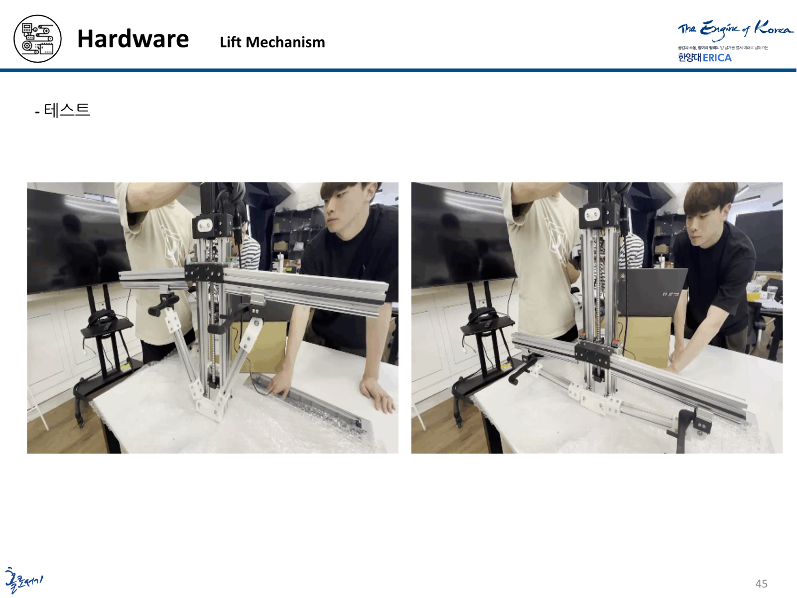
The capstone replaces the earlier manipulator concept with a dedicated mechanism driven by a stepper motor and linear stage. The linkage lifts the scooter, and a servo-driven gripper secures it for the intended transport step.
ROS 2 publisher–subscriber messages coordinate the mechanism with docking and navigation. After receiving docking_msg, the Raspberry Pi drives the stepper until a limit switch indicates the upper position. The control sequence then operates the gripper and issues the transition for travel toward the parking zone.
The prototype work includes bench tests of the lift and gripper, along with the navigation, perception, and docking tests described above.
Contribution
I worked on outdoor navigation and sensor fusion. My contribution focused on GPS-waypoint navigation with ROS 2 Nav2 and integrating GPS, IMU, and wheel-odometry observations through the robot_localization framework. I worked on the positioning and navigation components that support the robot’s movement through the outdoor test environment.